SmartRidge – Hip Roof Ventilation Instructions
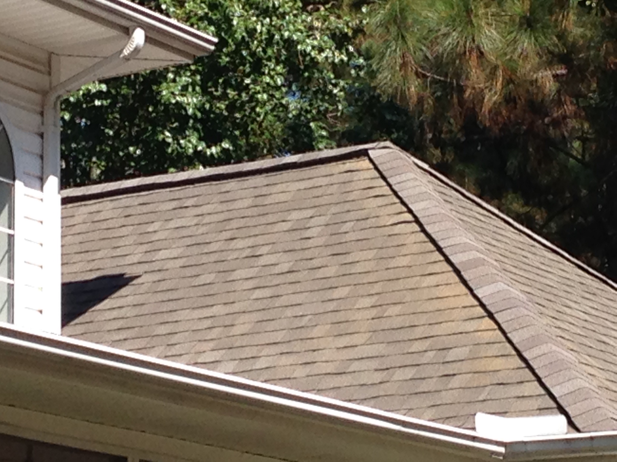
A finished look of a properly ventilation hip roof.
Creating Wafer Cuts on a Hip Roof
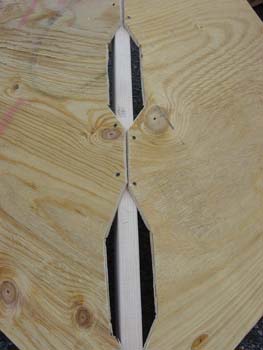
Step 1
Step 1.
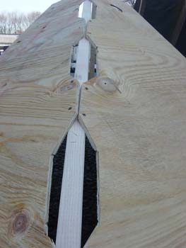
Full sheets showing hip vents 3.5” wide ‘wafer’ cuts by 12” long with 6” solid plywood intervals (as shown) between each opening, with upper and lower plywood edges solid (no cuts) for strength of the roof deck. Angle plywood length is approx. 60” as shown.
Step 2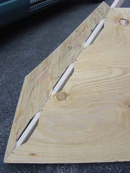
Step 2.
Wafer cuts showing top and bottom uncut for 6” to achieve cross grain strength and the cut out with 1.5” Hip Rafter has 1” air slots allowing air to flow out.
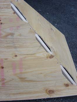
Step 3
Step 3.
Another wafer cut picture showing 3 ½ “ overall cut (1 ¾ “ each side)
Step 4
Step 4.
Wafer cut showing two nails per uncut section (6” uncut, 12” wafer cut)
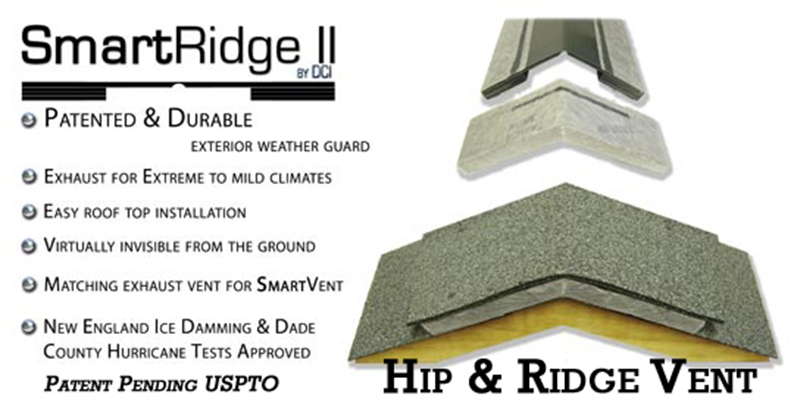
SmartRidge II Installation Hip Roof Ventilation
Installation of the SmartRidge Tapered End Cap:
(No Cutting of the End Cap is required. Simply nail it down.)
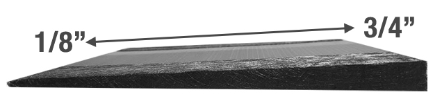
Figure 1
Step 1.
Ensure the area to be vented has been properly cut out and air flow requirements are met (refer to wafer cut hip diagram). Also ensure the shingles on each roof plane are previously installed per manufacturer’s directions and shingle and underlayment cutouts for the wafer cuts have been completed. NOTE: At least 1-36” course of the required underlayment at the soffit/eave area must not be cut around wafer cuts at the hip for waterproofing. Some regions require 2-36” courses of ice shield not cut at hip. The SmartRidge Tapered End Cap is tapered from 3/4” to 1/8” and the fabric edge always shows after installation with smooth side of vent facing up. It is hinged in the center and universal for right or left installation.
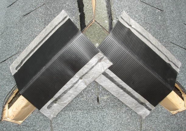
Figure 2
Step 2
Shows the SmartRidge Tapered End Caps being installed centered about 2” down from the Hip/Ridge peak applied on the hips and overlapped at the small 1/8” edge of each end cap. The 3/4” thicker edge of the Tapered End Cap is facing down slope so it butts against the not yet installed 3/4” SmartRidge II ridge vent. The overlap varies with the roof pitch. Six (6) nails per end cap with one (1) at each corner.
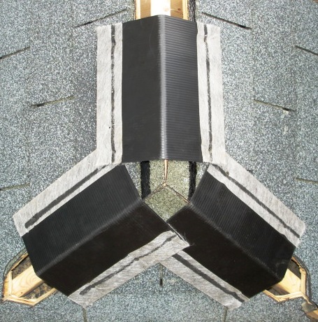
Figure 3
Step 3
Apply the third Tapered End Cap as shown centered on the roof ridge. Start with the small 1/8” end overlapping the previously installed hip end caps and also about 2” away from the peak junction of the Hip/Ridge point. Nails should be at the four corners and two between on the side edges. Additional nails can be used to form the vent as desired. The thicker edge of the vent will butt against the 3/4” SmartRidge II ridge and hip vent yet to be installed.
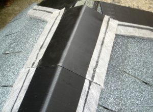
Figure 4
Step 4
Install the SmartRidge II ridge and hip vents by simply butting the pieces to the Tapered End Caps. Nail as required. Use SmartRidge Tapered End Caps to stop SR II at any location on the ridge or hip.
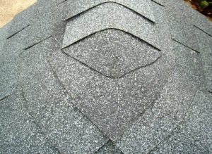
Figure 5
Step 5
Install cap shingles continually and over the Tapered end caps and SmartRidge II ridge and hip vents per manufacturer’s installation guide.
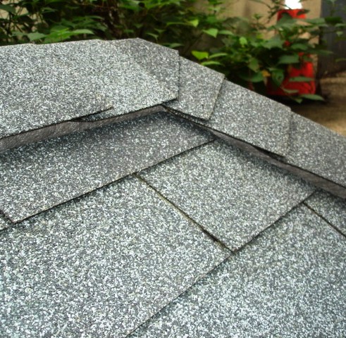
Figure 6
Step 6
Ensure cap shingles are cut to fit at the Hip/Ridge junction and are weatherproof. The vent installation is complete and creates a smooth transition on your hips and ridges.
Notes:
-Many areas of use are shown below. Use to end any vent run.
-Can be installed anywhere along hips and ridges.
-Use the End Caps for Gable Ends, Chimneys, Valleys & Dormers
-Nails should always penetrate through wood roof sheathing.
-Use on hips and ridges and around dormers, chimneys, near valleys and
at gable ends to hide swayback gable ends.
Do you have questions about SmartRidge II?
Please fill out the form below and we will be glad to help!
Need to translate?